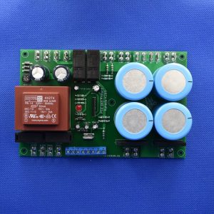
Description
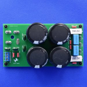
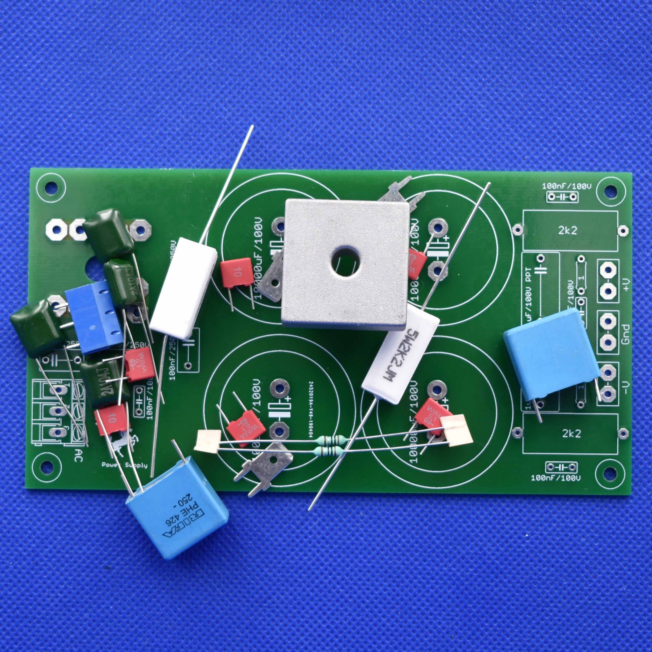
The circuit is very simple with high quality components included in kit:
Bridge rectifier to arrive at this model did a research, about which bridge rectifier for tin current was available in the market. I found this template which can be Kbpc2510 (25A), Kbpc3510 (35A), Kbpc5010 (50A). It has low cost and supports high current, a heatsink can be added in some cases. Only assembly on PCB is different.
The connectors must be adequate to withstand the current.
The resistors R1 and R2 – are 5W of power and serve to drain large electrolytic capacitors when the power is turned off. These resistors must be soldered away from the board.
The capacitors C11, C12 are for filtering high frequency noise at the output of the rectifier bridge
The capacitors C7, C9, C10, C11 – are high-value electrolytic capacitors used to supply high current demand and stabilize the power supply to minimize low frequency fluctuation.
C15 and C16 should be of good quality polyester film to filter out high frequency noises.
C13 and C14 together with R3 and R4 serves to decouple the large electrolytic capacitors and reduce the impedance.
C1 and C2 – are for filtering high frequency noises from the transformer secondary.
C3 to C6 – In parallel with the diodes of the bridge rectifier, are to filter noise coming from the junction of the diodes in addition to filter high frequency noises.
IMPORTANT:

